In order to have mvparts include entities that are thinner, thicker, a different color, or that do not plot, we have to take some steps...
I have found that this is best accomplished after the mvpart has been completely created. To create an mvpart, you can follow the steps outlined here: http://www.geniusoftllc.com/mvparts/create.asp
Assuming the mvpart is already created, starting from a blank AutoCAD screen...
1. Open the mvpart .dwg file. For example, C:\Documents and Settings\All Users\Application Data\Autodesk\ACD-MEP 2009\enu\Aecb Catalogs\US Imperial\MvParts\Mechanical\Roof Mounted AC Units\Gas Fired.dwg
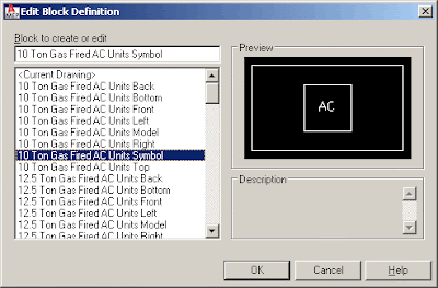
2. At the command prompt, type "BEDIT", select one of the "Symbol" blocks and click "OK" (for example, the 10 Ton unit) - the reason we edit the Symbol block is because it allows different lineweights, colors, etc.

3. Edit the block as needed to add clearance lines, hidden, lightweight lines, non-plot text, etc., save the changes and close the block editor.
4. Save and Close the Gas Fired.dwg drawing.
5. Regenerate the mvpart Catalog (command: )
6. Ensure that your display settings will show the Symbol block - to see how to do this, visit http://www.geniusoftllc.com/mvparts/videos/display.asp
7. Insert the Gas Fired mvpart and verify that the "pretty" entities are showing up.

No comments:
Post a Comment